How to Read Floor Plans

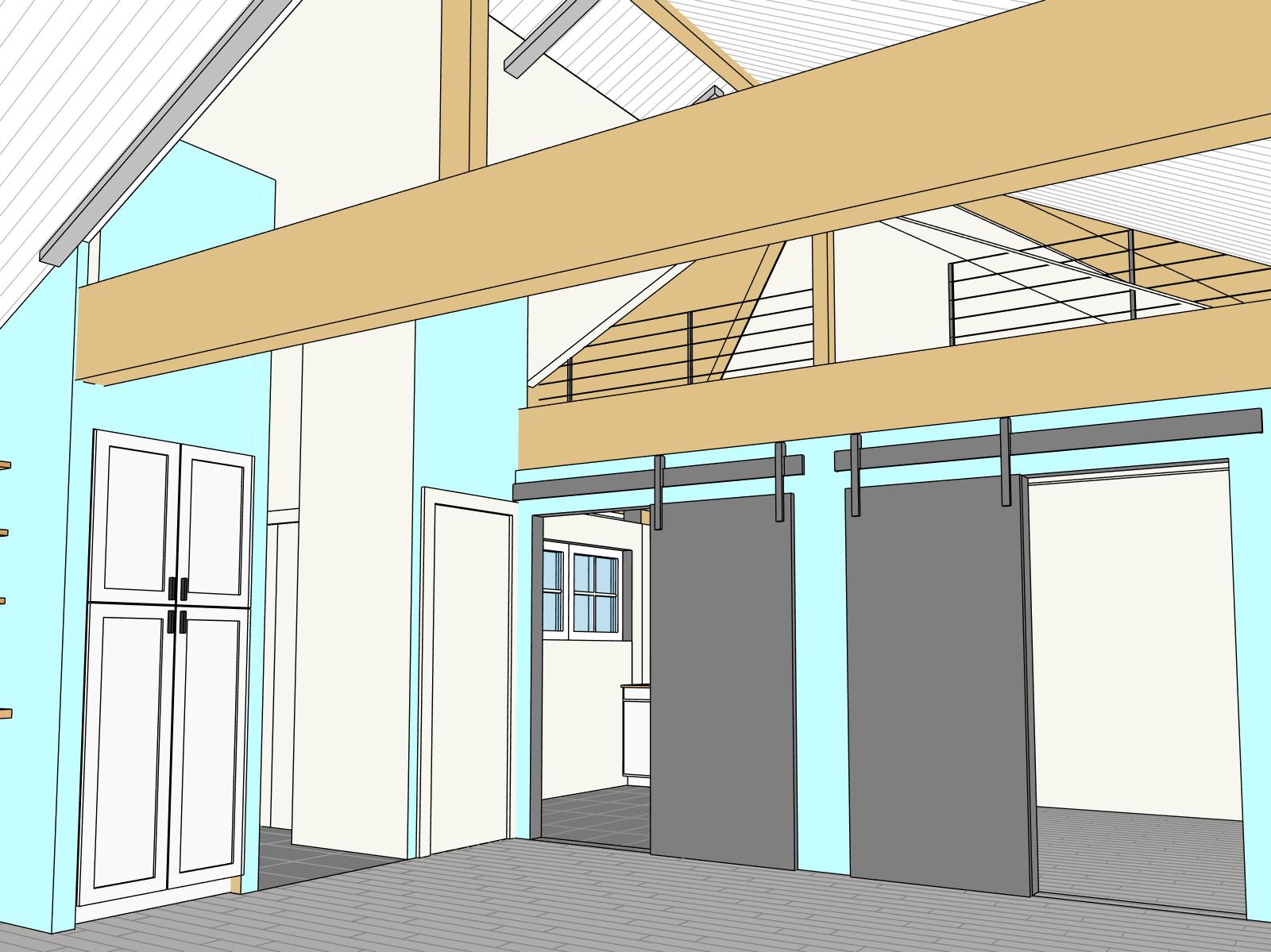
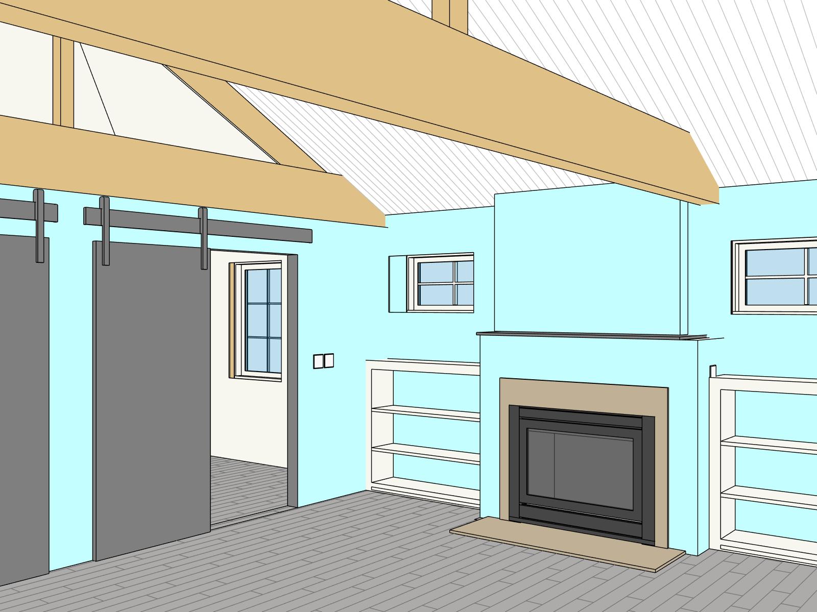
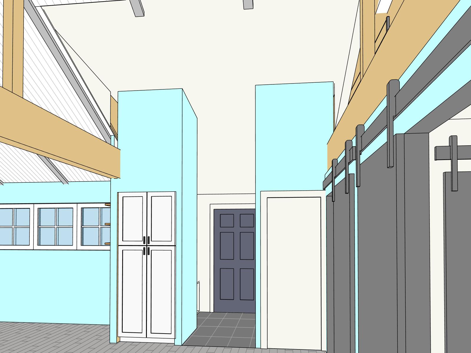
Throughout your home renovation project your architect should be able to provide you with 3D floor plans and other 3D images of the design. These are incredibly helpful for all involved, especially at the preliminary design stage. However, to receive permits and to have your project built, you will need a comprehensive set of construction documents.  There is a lot of information that needs to be conveyed and the bulk of this information gets conveyed in plans, sections and elevations. These are 2d drawings that are packed with information, and many people have difficulty understanding how to read these drawings.

This post will cover how to read your floor plans. Floor plans are presented as a view from above looking down at the floor. It is assumed that the plan is “cut” at about 48” above the floor.

The primary goal of the floor plan is to provide information about the location and relationship of the spaces you want to be built. We define these relationships by locating walls, doors, windows and other items. One of the key elements of reading your floor plan is to identify the dimension strings. These sets of dimensions give instructions about where to place walls and how thick those walls are. There will usually be multiple strings of dimensions next to each other, as it helps to separate things like the location of windows from the overall dimensions.

Another important feature in floor plans are plain language text notes. These are brief explanations of something to which the architect wants to draw attention. Text notes are used to point out existing items, atypical conditions or special instructions to the builder.

In addition to dimensions and notes there are often special symbols on a plan that direct your attention to another drawing or a schedule. Marks near windows and doors, often a single letter or a few numbers, indicate the type of window or door. This mark will match a line on schedule, which is a spreadsheet containing additional information. For example, if you see a “B” in a hexagon next to a window you can refer to the window schedule to see that window “B” is 36” wide and 72” tall and is made of wood, etc. Some other symbols found on plans include section and elevation markers. These drawings provide information about the vertical separation between spaces, exterior siding, roof pitches, etc, that can’t be shown on a floor plan. Floor plans will have references to these drawings though, so you can understand where those drawings are in the context of your design. A section marker is usually a circle with an arrow, and a sequence of numbers explaining which page the drawing is on.

Did you have any specific questions that weren't covered here? Leave a comment or send us an email. Check back soon for how to read your sections and elevations!

Home Office Renovation Update

“Plans are useless, planning is indispensable.” This quote, or a similar variation, is attributed to President Eisenhower, and refers to his preparations for battle when he was a General. The same can be said of any home renovation project.

A good set of design drawings is vital to the success of the project for a number of reasons. Your home renovation plans will help you acquire building permits, receive accurate bids from contractors and help you understand the size of your future space. No set of plans is perfect though, and as the project moves from design through construction, things change. Your plans must change with them, and it’s for this reason that planning is just as important as the actual construction drawings.

The process of creating your plans will help you and your architect become more familiar with your project. This will pay dividends not only through inspiring new ideas, but by helping all parties involved become more familiar with the project. The more you know about the project, the more things you consider in the planning phase, the fewer, or less disruptive, surprises you’ll encounter when the project begins to be built.

An exciting project we currently have under construction is a large carriage house that is being converted into a home office. We began the project with a site visit and then built a 3D model of the carriage house based on measurements and pictures. Through the planning process we worked closely with the owners to customize the space to fit their needs. As construction began however, the clients recognized new opportunities for the space that had not been considered. Due to the time and effort we spent in planning, we were able to more easily integrate these new ideas into updated construction documents. These ideas included, among other things, additional storage, a skylight and a new exterior door.

See the sliding images on this page for some comparison images showing the original design and what is actually being built.

BIM/REVIT: See Your Future Home in 3D

At Mangan Group, we design all projects, from restaurants to small additions to whole house remodels in an advanced Building Information Modeling (BIM) software called Revit. There are many benefits of using a BIM software instead of traditional 2D drafting software, but our clients are particularly fond of Revit’s 3D capabilities. We have the ability to instantly place a virtual camera at any point in the house and get immediate visual feedback about the space.

We can also instantly create 3D floor plans, which help architects and clients alike understand the size and dimensions of a space with far more awareness than a traditional 2D drawing.

During a recent conference call with a client, we were able to remotely share our screen and rotate their house in real time. This was incredibly valuable for the client, and ensured everyone was seeing and understanding the same thing.

Check out some of these images from the design phase of our Logan Circle project and see how they match up with the actual finished product!

FLOOR PLAN SHOWING CAMERA BEING POSITIONED

3D VIEW CREATED FROM FLOOR PLAN

FINISHED DESIGN!

THE FINISHED DESIGN

FULL 3D VIEW WITH CUTAWAY VIEWS